Coordinate Systems: From definitions to real-life

Introduction
Currently, the growth of software tools and machinery for the AEC industry is increasing every day. In daily construction operations, machines and workers are using more and more the GNSS (Global Navigation Satellite System) for site positioning and so on. Architect’s and engineer’s practices are dominated by the software modeling tools that exist in the market. Professionals need to understand the concept of coordinate systems and their usage as this can help in tasks like reducing site and modeling errors and eliminating downtime.
What is a coordinate system?
In geometry, a coordinate system is a system of n-tuples or coordinates to uniquely place a point or other geometric element in any N-dimensional Euclidean space Rⁿ. Fermat and Descartes discovered the idea of using linear algebra to address geometrical problems on coordinate systems to locate a point in space.
Each coordinate system serves a specific case. In this article, we will define the most common ones and provide real-life use cases.
Number Line
We can imagine this system as a derivative of a 1D coordinate system, the line’s direction is the axis, and the coordinates of each point are a real number. The value is the negative or positive signed distance from the point of origin P0 to the point Pn.
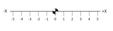
The most common example of something like this is a rule or a T-square.
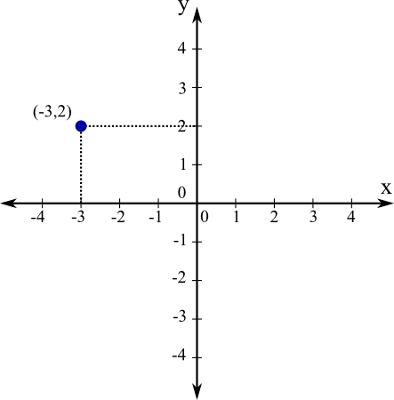
The Cartesian Coordinate System
In two dimensions, two perpendicular number lines make up the XY or Cartesian coordinate plane. They are the horizontal or X lines, formally called the abscissa, and the vertical or Y lines, formally called the ordinate.
Any point on the coordinate plane, whether integral, fractional, rational, or irrational, is characterized by its coordinates (X, Y). Each coordinate is the signed distance from the point of origin along the corresponding axis to the position of the point.
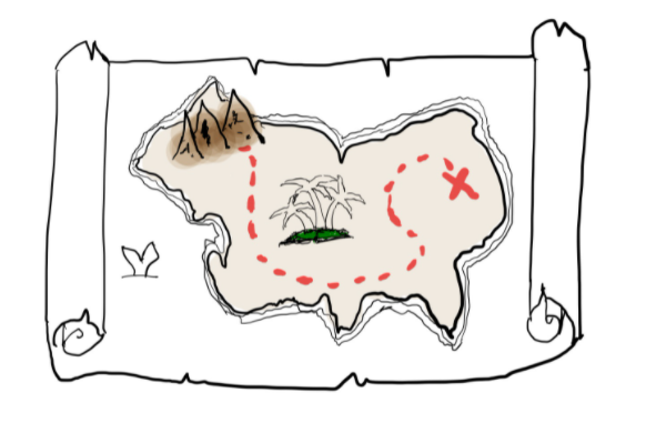
For instance, pirates used maps to hunt treasures. Well, guess what? They operated on the “Cartesian Coordinate System” Why? It’s the simplest to interpret. Locating points in space and calculating distances from one point to another was a general practice from which they benefitted.
In three dimensions, a third tuple adds up and represents the Z-axis of the plane. So the point representation looks as follows P(X, Y, Z). Each CAD modeling software follows a particular order of tuples.
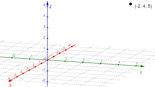
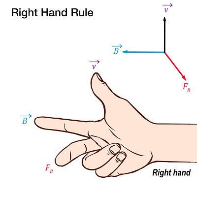
Now depending on the order and direction of the coordinates/tuples, the coordinate system is applied as a right-hand rule or left-hand rule.
Which way is up?
As architects or engineers, we typically tend to think that in terms of a construction building: X and Y are the horizontal coordinates that will define the distances on a certain level, and Z is the vertical distance. But developers tend to think how these coordinates relate to a computer screen, so X and Z are the horizontal coordinates and Y ends up as the vertical component.
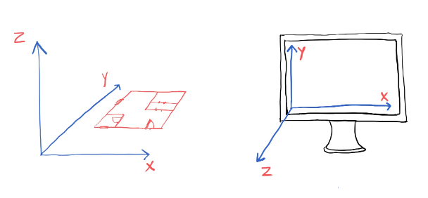
For instance, Revit, Rhinoceros, AutoCAD, 3Dmax, and more use the order XYZ where the Z is the third tuple. On the other hand, Navisworks, three.js, Unity, and Minecraft use XZY, where Y is the vertical component.
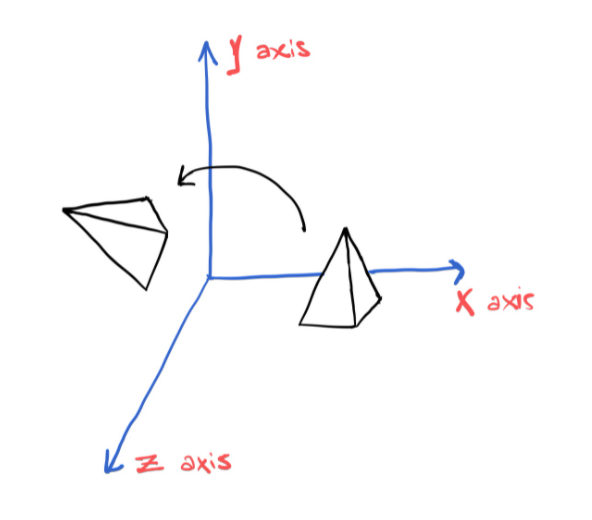
This is important because when exporting a model from one software to another, you can consider the order of the axis; otherwise, you might end up with a rotated model.
The polar coordinate system
There are other ways to locate an object in space. For more complex cases where we are operating on Surfaces, Curved lines, and Spaces, another system derived from a circle is used and is the “Polar Coordinate System,” It is commonly used for great modeling systems which involve radial symmetry, forces and includes a wide range of application in engineering and physics such as Gravitational fields, magnetic fields, radio signals, astronomy, and so on…
The coordinates point are represented as follows: P(r, θ). We can imagine the point as the pole of rotation and the ray of the axis of rotation, and we define it as follows:
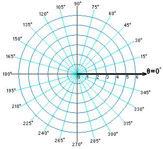
- The x-coordinate: r is the signed distance from the point of origin P(0,0,0) of the plane.
- The y-coordinate: θ is the rotation angle(counter-clockwise) on the z-axis of the plane.
Polar coordinate systems can be used, for example, in AutoCAD to define points based on a known center of a machinery piece and then the distances and angles to define its vertices. There is even a polar 3D printer that exclusively works on circular print beds.
Spherical & Cylindrical coordinate systems
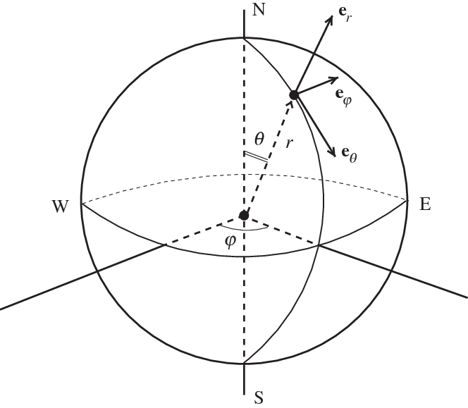
Spherical and Cylindrical systems add a third dimension on top of the Polar coordinate system simply by adding a third tuple called phi. Geographic systems are translated from Spherical coordinate systems. Coordinates are typically expressed as Northing, Easting, and Elevation and are used in lines, surfaces, and features. However, in construction machinery, GNSS works in Latitude, Longitude, and Height in a global system.
We define it as follows:
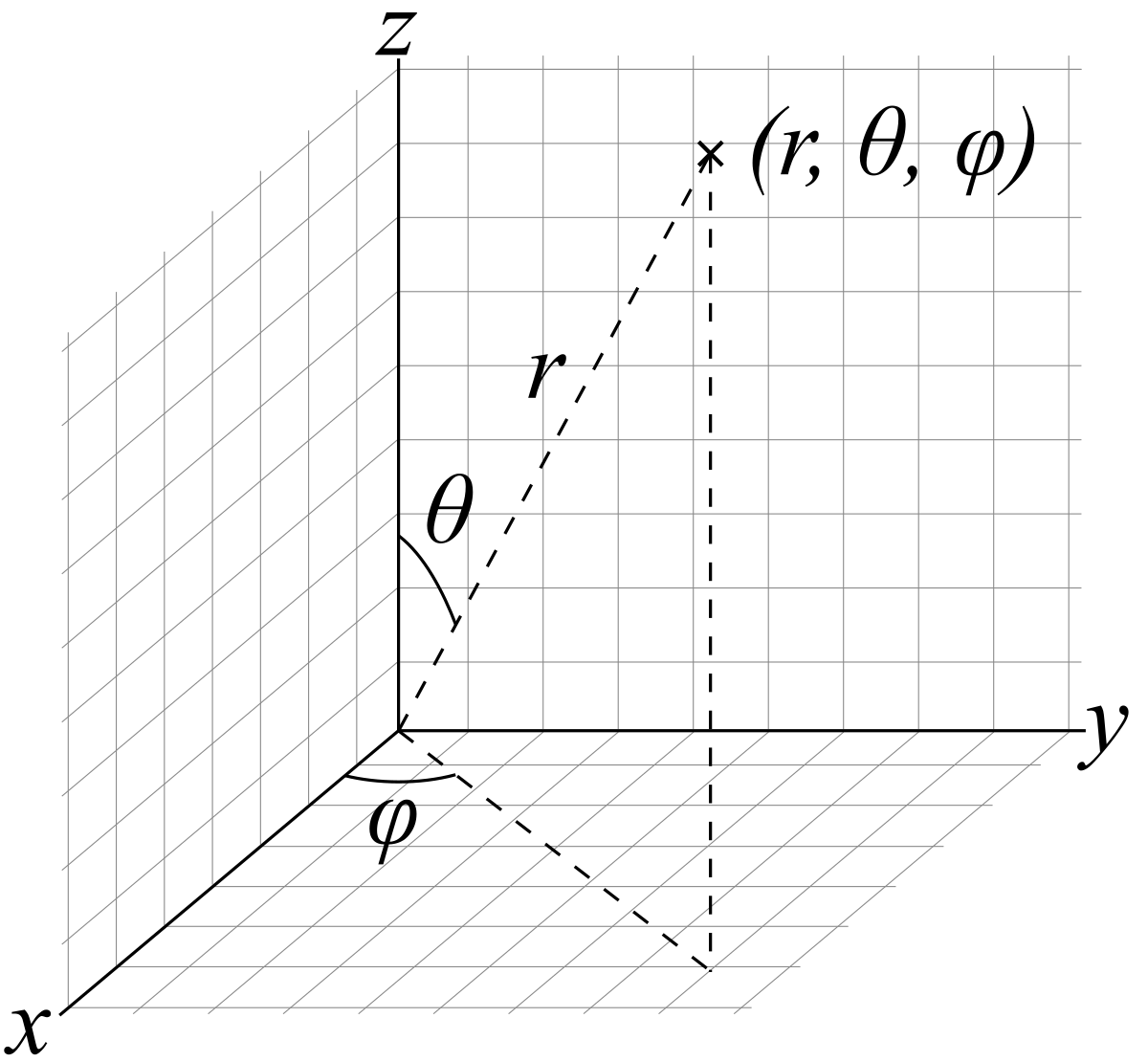
- The x-coordinate: r is the distance from the origin P(0,0,0) of the plane.
- The y-coordinate: θ is the rotation angle from the plane’s z-axis.
- The z-coordinate: φ is the rotation angle from the plane’s x-axis.
The first tuple, r, represents the earth’s radius. The latitude is the θ, whereas the longitude means the φ.
In the case where φ is constant, the point will be placed anywhere in the cylinder of radius r.
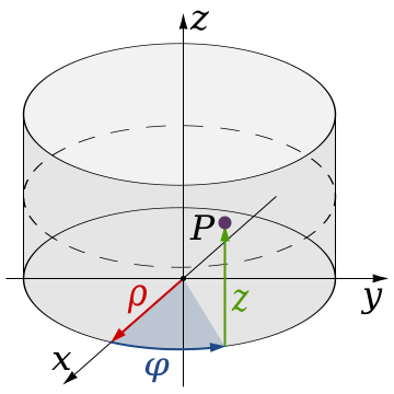
So, in this case, if the z-coordinate varies in the range 0 ≤ φ ≤ 2π, the point will be located anywhere in the sphere of radius r.
Due to the fact that spherical coordinates are used to represent elements located on a sphere, our planet is the perfect fit for this. That is why platforms like Mapbox or Google Earth use it to define the location of buildings, roads, environments, and more data related to geography and urbanism.
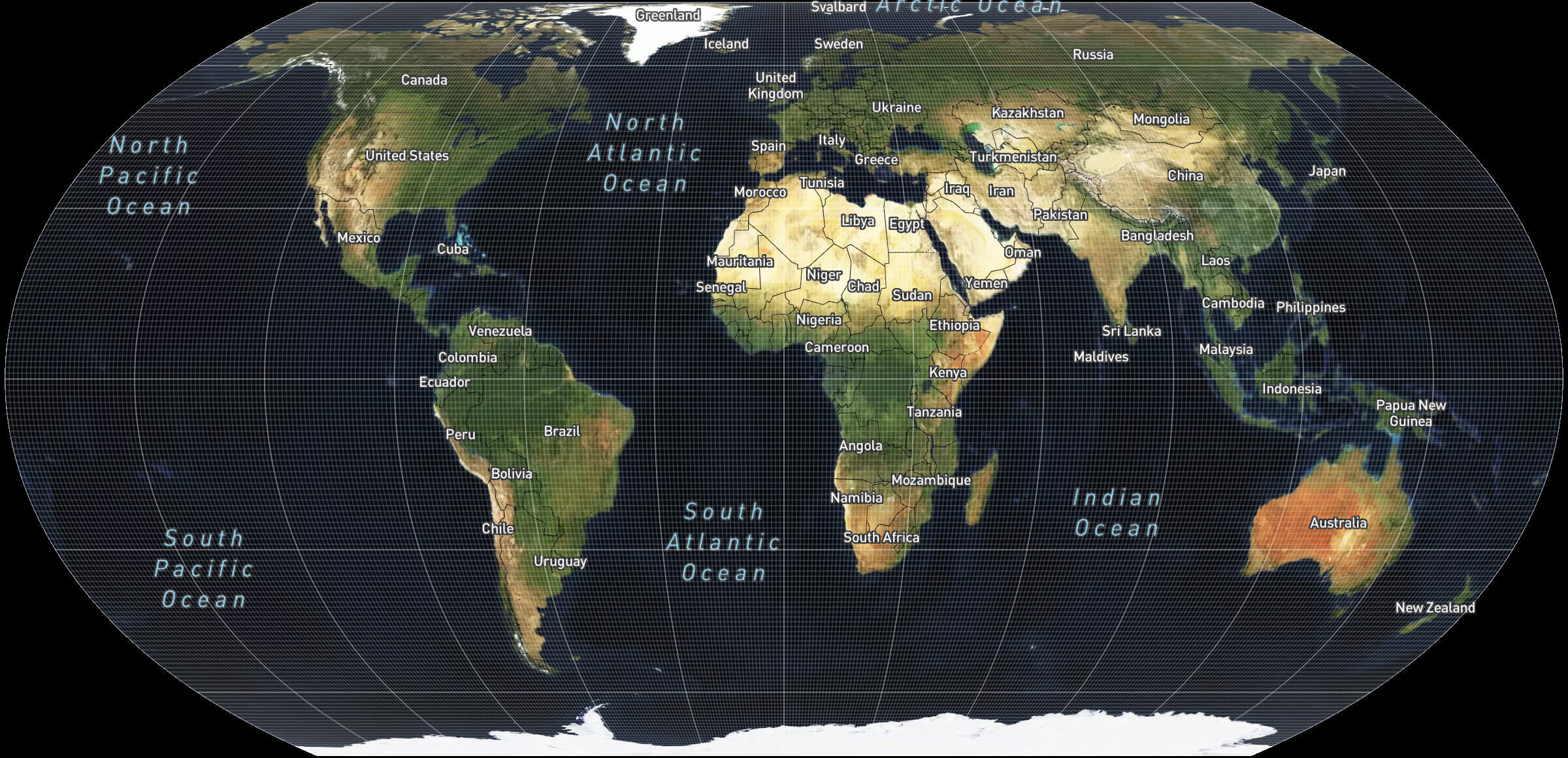
It is also essential to remember that when dealing with buildings and cities, software developers typically represent them as geographic coordinates, which is a translation of the spherical coordinate system where the latitude and longitude are a conversion of real numbers to degrees.
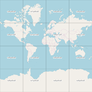
Examples of where this happens are Revit to define global coordinates or OSM that allow you to render everything in a flat environment dividing the world into tiles.
From Geometry to Real-life
On the AEC, we are so used to dealing with 3D models that we take the coordinate systems for granted. Still, the reality is that the more you want to relate different programs or even different sources of data (e.g., Real-world data and project data in Revit), the more you need to understand them to be able to make your workflows perform correctly on your software ecosystem.
This is the start of a series of posts where we expose how common mathematical concepts work and how to take advantage of them. In the following article, we will talk about, Points and Vectors, so stay tuned!

Pablo Derendinger
https://www.e-verse.comI'm an Architect who decided to make his life easier by coding. Curious by nature, I approach challenges armed with lateral thinking and a few humble programming skills. Love to work with passioned people and push the boundaries of the industry. Bring me your problems/Impossible is possible, but it takes more time.