Points and vectors in computational design

Simple explanation of Point and Vectors in Computational Design
Introduction
In our previous article, we delved into the topic of Coordinate Systems. This time, we will address how the integration of Points and Vectors in computational design can enhance the optimization and refinement of computer-aided design processes in the AEC industry. We will explain their basic mathematical and graphical representations and introduce their usage in code.
Furthermore, we will offer a hands-on demonstration in Grasshopper3D, a visual programming platform, featuring various functions that can greatly enhance one’s design proficiency. Our objective is to build the given facade entirely from the ground up utilizing these principles.
What is the definition of Point in geometry?
Let’s explore the geometric concept of a Point. A point is a position located in any dimensional space or a flat plane, such as 2D designs(x,y) or 3D space(x,y,z), denoted by its coordinates, typically represented as an array of numbers. It is measured relative to the origin points (0,0 or 0,0,0 respectively) of the coordinate system.
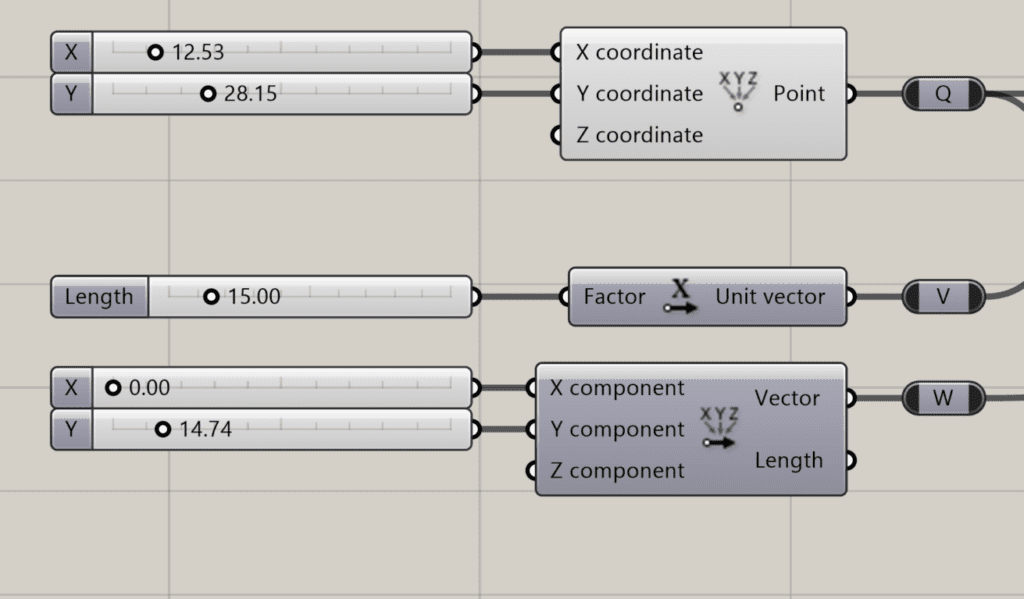
Programmatically it can be created by entering its coordinates represented as properties. For instance, in Grasshopper3D, it can be created by X, Y, and Z coordinates passed as arguments to the construct point component. Below, a graphical representation of the latter shown in the tool, its position in space is manipulated by modifying its inputs.
What is a Vector in Geometry
A vector is a mathematical object representing a magnitude and direction in a dimensional space. It is given by an array of numbers, for example [0.25, 0.25, 0]. In the context of 3D modeling, vectors play a crucial role in defining shapes and movements in three-dimensional space.
Geometrically, it can be represented by a straight line whose length is the magnitude and an arrow at the end that points to the direction of the vector. The magnitude of a vector can be computed using the Pythagorean Theorem (a^2+b^2=v^2), where a and b are the components of the vector.
It can be initialized from two points A and B by subtracting one from another. Therefore, the order of the operation matters to determine the direction of the vector. If you reverse the order instead, you will get a vector that starts at point B and ends at point A. This vector will have the same magnitude, but it will be pointing in the opposite direction. In Grasshopper3D it will look like something in the animated image below.
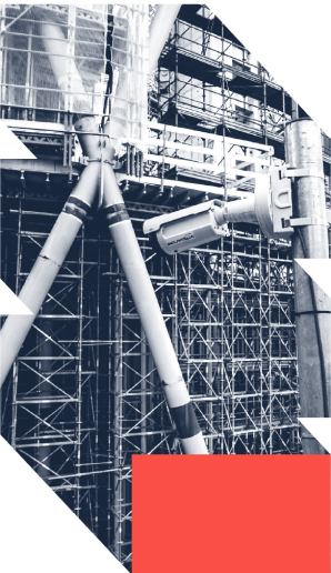
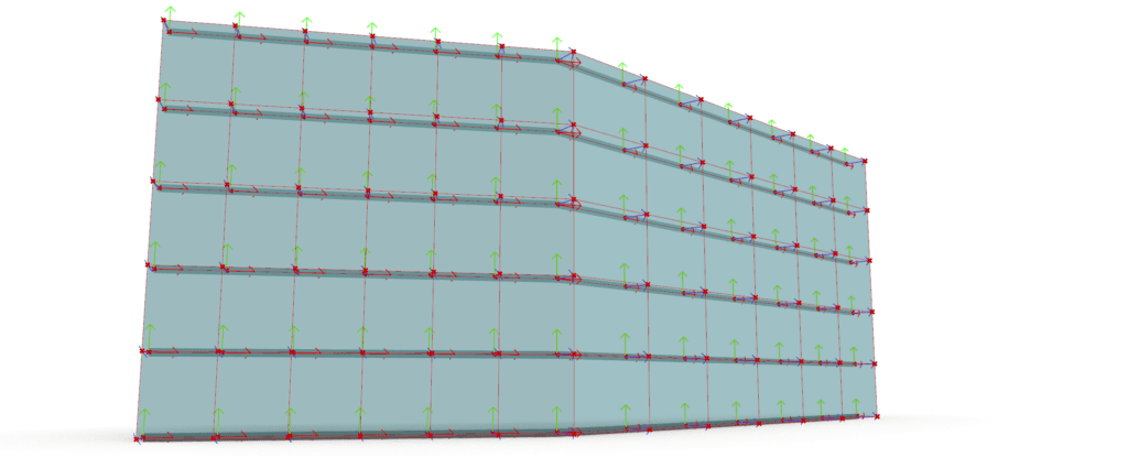
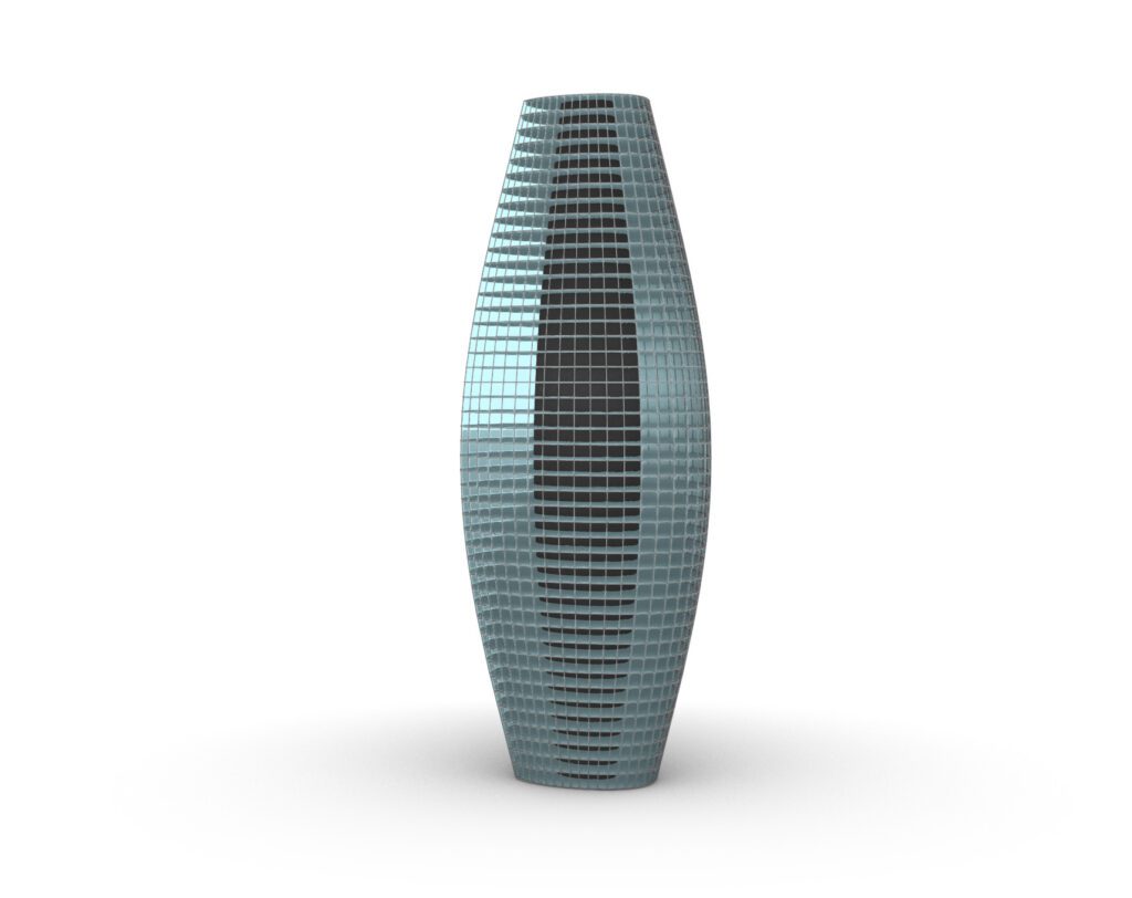
Vectors are widely used in the AEC industry for a variety of tasks. Considering the example of the façade we’ll go through and the comprehension of points and vectors definitions, along with the corresponding code, it can be extended to more intricate forms, like the tower below.
How can we benefit from Vectors and Points in computer aided drafting and design?
Using algorithmic modeling techniques, designers can efficiently create and manipulate complex geometries using points and vectors. Designing a double skin façade requires a thorough understanding of vectors and their operations. They are essential computational design tools for architects and engineers to visualize and manipulate various elements of a planar surface or a façade, such as the position and orientation of panels, the shape of openings, and the direction of airflow, determining the angle of a panel relative to the beam, or calculating the pressure differential across a façade and much more. Now, we will explore how vectors and their operations can be used to solve design problems and create efficient and aesthetically pleasing double skin facades.
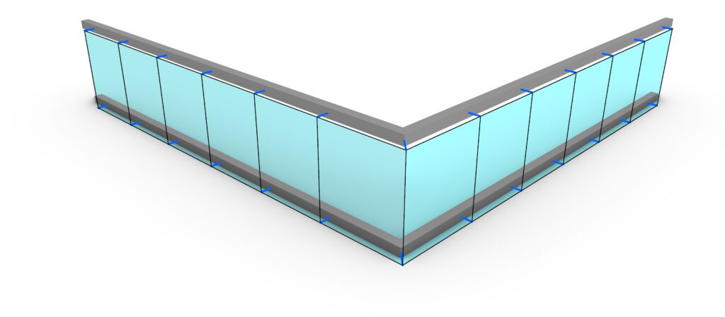
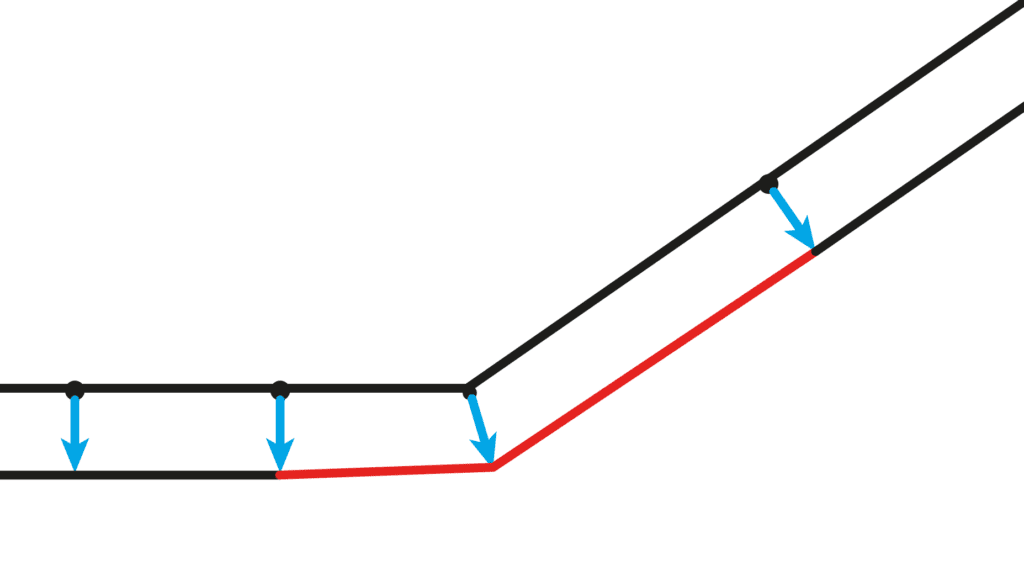
- One of the primary challenges in this scenario is to ensure that the curtain wall’s mullions are perpendicular to the building’s outer beam as shown below.
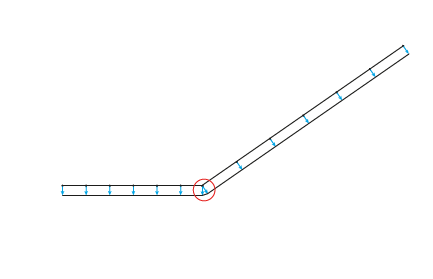
- Another major issue arises at corners and especially where the angle is not right (90 degrees) and the height needs to be calculated, highlighted in red. It leads to the axis of the curtain wall not being parallel to the beam’s axis.
As I prepare to embark on this vector explanation, I will provide a clear and comprehensive guide to ensure that you have a full understanding of the process. So, let’s jump right in!
In Grasshopper3D we could use the following pseudo code to solve the problems:
- Vectors/Points Association (Point translation) to draw the beam’s axis.
- Use the cross-product to determine the normal vector to the beam at each mullion location.
- Vectors addition to obtaining the bisector vector.
- Apply trigonometry to calculate the height of the bisectors and ensure that the axis of the wall is parallel aligned to the axis of the beam.
Given a starting point Q and two vectors V (blue) and W (red) as initial inputs, we can benefit from them to create a restrictive relationship between one another.
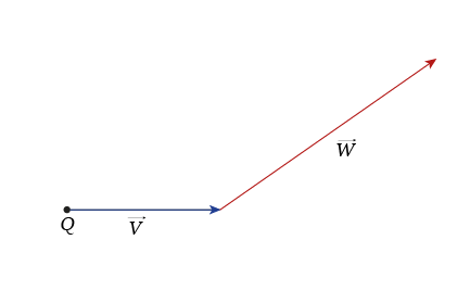
Consequently, this ensures that their correlation remains consistent whenever the coordinates are modified. For a better interpretation, a graphical representations of the instructions is given above.
- The translation of the point Q along the vector v results in a new point P. It is a fundamental command in CAD software. Here, we use addition operation to obtain points P and R.
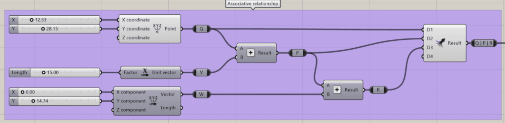
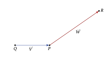
Once we have obtained P by summing Q and V, then we can sum the point P to the vector W to finally obtain the point R as highlighted in the screenshot above. This will enable us to draw a line that represents the beams’ axis of vectors V and W as shown in the graph below.
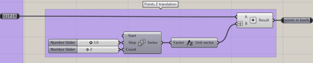
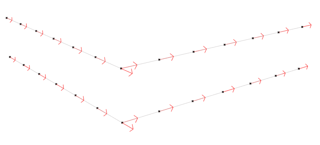
Another vector translation to elevate the beams in height. In order to do so, we need an incrementing equally distant series of numbers, where each number is multiplied by the Z unit vector. Thus, adding each point to each Z-vector will result into nested lists where for each level a list of points. In the screenshot below, we have a count of 2 numbers, which will output two lists of three points each. Have in mind that incrementing the count will lead into more levels.
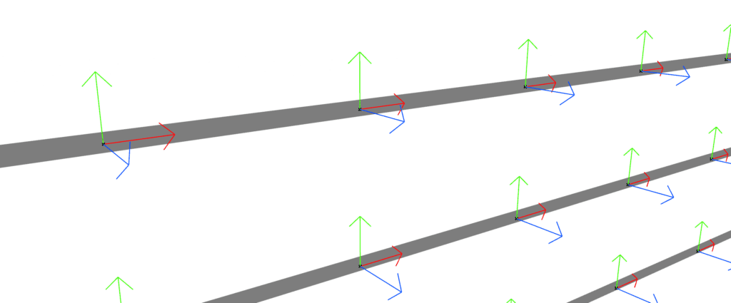
Before starting to solve the next problem, we need to draw a line that represents the beam and get the tangent vectors on each mullion’s position vector. By using the Grasshopper3D’s native component called Divide Curve, we can get a list of equality distant points and the tangent vector at each location as shown below.
2. The cross product in mathematics is an operation that calculates the perpendicular vector to two given ones such as a and b, denoted by the cross x sign. Its geometrical representation is shown in the graph below.
The equation can be used to find the magnitude and direction of the result. The formula involves multiplying the length of a and b by the sine of the internal angle θ between them. The direction of the resulting vector is determined by the right-hand rule, As shown below, it states that if you curl the fingers of your right hand in the direction of a and then towards b, your thumb will point in the direction of a* x *b.
After applying the curve subdivision function to determine the location and the tangent (in red) of each mullion, the Normal (in blue) can be finally retrieved by calculating the cross-product of the tangent and the Z unit.
Although the corner normals are correctly computed, this affects the discontinuity of the curtain panel relative to the beam. To achieve a straight behavior, in the next step, the average vector between both is calculated, and the height is finally retrieved by the help of vector algebra.
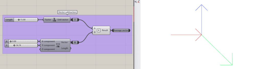
3. Vector addition/subtraction are other mathematical operations that returns a new vector by adding or subtracting two given vectors.
In our example, this function is applied over the normal at the corner to get the average. Since our initial vector v (in red) points towards w (in blue), we can apply the subtraction to get the average (in green).
However, calculating its hypotenuse is still necessary to achieve the desired alignment as shown below.
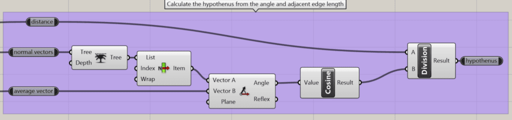
4. In our example, knowing the angle θ and one side d of a right triangle, we can use the trigonometry and cosine function to calculate the length of the hypotenuse h, which is the third side of the triangle.
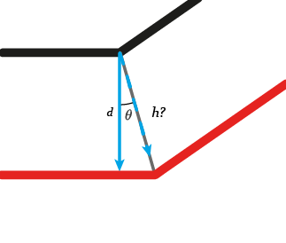
To get h accordingly, in Grasshopper3D we can divide the distance over the cosine of the angle measured between the normal d and the average h.
5. In our example, we can use scalar operations to set the length of the mullions. Scalar operations are another important , it is simply the multiplication or division of a vector’s coordinates by a real number. To scale the length of a vector, we can use scalar multiplication with the desired distance as the scalar value. It will result in a vector of the desired length in the same direction as the original vector.
To perform scalar multiplication, we must first normalize the vector by dividing its coordinates by length to obtain a . The has a length of 1 and points in the same direction as the . Then, we can multiply the by the distance to obtain a vector of the desired length.
Conclusion
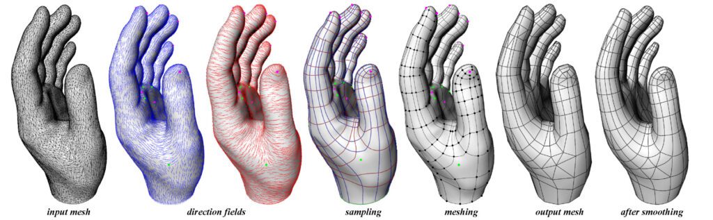
Points and Vectors are crucial concepts in computer-aided design, and understanding them is essential for effective problem-solving. Their usage in programming languages, such as Grasshopper3D or C#, enhances the optimization and refinement of design spaces and parametric architecture processes. Hence, they have several applications in the AEC industry, including structural analysis, computational methods, fluid dynamics, and more. Another usage for vectors and operations such as direction fields in re-meshing techniques for digital fabrication.
In our next article, we will delve deeper into meshes and parametric equations, if you would like to download the whole Grasshopper script click here.